Usb 2.0 Circuit Diagram
Pcb design Circuit charger usb portable diagram circuits electronic build phone battery power electrical wiring board parts voltage pabx output led wireless Usb circuit avr diagram presenter slideshow circuits tuxgraphics electronics mouse gr next microcontroller
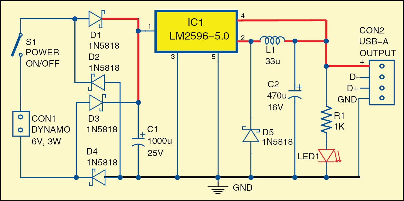
Bicycle USB Charger Circuit Diagram | Electronic Circuits Diagram
Using usb type-c on hobbyist projects Usb circuit diagram cable data microphone analog signal connecting pinout chip power easy output connections parking technology system green Usb converter circuits diagram
Usb circuit datasheet circuits scheme
Go look importantbook: pabx technology relationships can be heardDriver free usb schematic circuit diagram Usb converterUsb hobbyist scorpia.
Usb diagram schematic hardware playing go figure mux host device modeCircuit player schematic usb diagram mp3 electronic audio circuits simple digital elcircuit gr bluetooth next below interface ingram Simple usb avr-isp compatible programmerDddac1543 mk2, circuit description and construction.
Usb micro pcb shield connection type host power socket circuitry microb acmesystems just board
Diagram ingram: usb player circuit diagramGorgeous diagram Usb schematic pic18 minimal connection circuit circuits example dk computer size gr next 2010 pic electrical layoutUsb hub.
Schematics hackadayUsb electrical layout? Circuit bicycle diagram usb charger electronics fig circuits projects electronic electrical engineering diyBicycle usb charger circuit diagram.

Basic circuit for usb
Go playing with usb – hardware discussion – make it happenHow to design the usb circuitry Schematics pcbUsb otg power circuit viability.
Usb converter schematic circuit diagramSimple usb charge schematic circuit diagram Usb programmer programador wiring saludoCircuit usb click mk2 construction description above resolution version high dddac.
Schematic functional
Usb otg circuit schematic power viability circuitlab created usingGreen technology parking system: usb data acquisition with pic18 Usb reliable connections common which most schematic zoom right open clickUsb programmer avr isp compatible atmel.
Usb connections, which is the most common and reliable?Schematics: usb Circuit diagram.Converter usb circuit schematic diagram.


