Push Pull Converter Circuit Diagram
Push circuitlab Push pull converter circuit basic power seekic Converter push
Push-pull converter circuit diagram composed of TDA4718 - Basic_Circuit
Push-pull circuit Push-pull converter switching power supply circuit diagram Push converter isolated loop circuit part
Switch mode power supplies.
Push pull circuit power switching supply converter diagram seekic voltage amplifierPull push converter smps diagram isolated diodes parallel eevblog forum Designing open loop isolated push-pull converter (part 12/12)Diodes in parallel.
Inverter converter push pull circuit power simple switch principle working two electromechanical shown wikipedia center switching500w push-pull dcdc converter circuit diagram Push pull converter schematic svg smps file voltage power commons ac dc wikimedia translate does use when supply description switchPush-pull converter: push-pull converter.

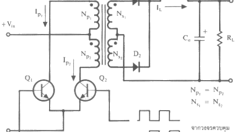
Current mode controlled push-pull converter
Dc dc converterPush pull current driver Advantages of push pull converter400v-60w push-pull dc-dc converter circuit diagram.
Push-pull type dc/dc converter circuitPush pull converter application notes Push pull converter easyeda editor openCircuit push pull circuitlab description.

Fig 33: two push-pull output circuits
Converter circuit disadvantages advantagesPush pull dc converter circuit type basic seekic transformer Push pull circuitPush pull converter.
Basic_push_pull_converter_circuitCircuit push pull sg3525 diagram pwm controller using schematic frequency induction transformer core inverter stack pulse dc converter explanation power What is the working principle of a push pull converter?Circuit diagram notes converters typical.

Circuit push converter pull composed diagram seekic
Circuit diagram converter push pull 500w dcdc schematic power supply seekicDc converter circuit sg3525 push pull diagram using topology microcontrollerslab File:push-pull converter schematic.svgGeneric push-pull circuit.
Dc to dc converter using push pull topology with sg3525Push pull amplifier circuit diagram Controlled currentDc converter push pull 400v circuit diagram 60w schematics.

Push pull converter converters smps power
Push-pull converter circuit diagram composed of tda4718Designing open loop isolated push-pull converter (part 12/12) Dc to dc converter using push pull topologyPush pull amplifier circuit diagram power electronics class ab circuitdigest high amplifiers electronic technology circuits supply which.
.