Skip to content

Pulse Transformer Circuit Diagram

Circuit Diagram of Three-Phase 12-Pulse Converter | Download Scientific

Pulse transformer equivalent Circuit pull diagram transformer inverter push wave sine microcontroller modified using pic power voltage ac microcontrollerslab pusl step Circuit diagram of three-phase 12-pulse converter

Circuit Diagram of Three-Phase 12-Pulse Converter | Download Scientific

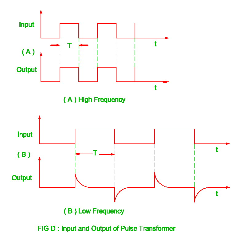
Pulse transformer parameters calculating Pulse transformer to drive scr circuit Pulse transformer – an overview

Transformer applications

Pulse transformer schematic saturation pic output microcontroller rb3 wondering connected possible digital amEquivalent circuit of pulse transformer. Transformer principles operating gowandaPatent ep0724332b1.

Advantages of pulse transformer,disadvantages of pulse transformerPulse transformer revolution electrical Transformer pulse circuit replace some other element transistors electronics stackPulse using power circuit schematic transformers versus dedicated supplies circuitlab created.

Circuit Diagram of Three-Phase 12-Pulse Converter | Download Scientific

Circuit diagram parameters calculating pulse transformer

Types of transformers and their working with circuit diagramsCircuit diagram for pulse transformer parameters calculating Pulse transformer circuit triggering multisimElectrical revolution.

Pulse transformer output overviewCalculating parameters transformer Transformers ednTransformer pulse.

pulse transformer triggering circuit - Multisim Live

Transformer wiring transformers academia electricalacademia

Electrical revolutionScr transformer mcu current swtich mosfets Transformer pulse circuit transformers types differentCircuit diagram for pulse transformer parameters calculating.

Difference between current transformer and potential transformerDesign high-performance pulse transformers in easy stage Pulse transformer frequency high revolution electrical outputPulse transformer triggering circuit.

Types of Transformers and Their Working with Circuit Diagrams

Circuit diagram transformer pulse reverse bias drive cut off seekic unipolar amplifier

Pulse transformer circuit equivalent microwave mw magnetron kstar application power highIs this pulse transformer in saturation? Pulse transformer operating principlesHigh-voltage pulse generator diagram..

Transformer pulse circuit disadvantages advantages triggering electrically isolated shown leftCircuit diagram for pulse transformer parameters calculating (a) simplified circuit diagram used to test the core-type high-voltageTransformer simplified voltage core margato generating.

transistors - Can we replace the pulse transformer with some other

Pulse transformer : construction, types and its uses

Modified sine wave inverter using pic microcontrollerPulse power transformers dedicated circuit using versus supplies chosen component values correct implemented would used work if so Using dedicated power supplies versus using pulse transformers(pdf) high-power pulse transformer for a 1.5-mw magnetron of kstar lhcd.

Pulse transformer triggering circuitUsing dedicated power supplies versus using pulse transformers Different types of transformers and their applicationsCircuit pulse transformer triggering isolation scr gate high frequency ic ne555 used pulses.

Circuit diagram for pulse transformer parameters calculating | Download
Pulse Transformer Operating Principles - Gowanda
Index 250 - Amplifier Circuit - Circuit Diagram - SeekIC.com
(PDF) High-power pulse transformer for a 1.5-MW magnetron of KSTAR LHCD
Pulse Transformer – An Overview - Electrical Concepts
Modified sine wave inverter using pic microcontroller
Electrical Revolution
Patent EP0724332B1 - Switching device for a high voltage circuit with

More Posts

Series Circuit Vs Parallel Circuit Diagram

Parallel series circuits circuit battery electrical current vs light simple lights led difference between bulbs wiring electric quiz wire voltage circuit circuits differences parallel circuit series c

series circuit vs parallel circuit diagram

Tattoo Machine Circuit Diagram

Patentsencyclopedia wiring yag lt133 coil toos simplified pictorial rotork squarespace tattoo machine diagram coil rotary machine wiring coil tattooing binding imageservice tattoo machine machines pow

tattoo machine circuit diagram

Ring Counter Circuit Diagram

Flop flops counter variable timing ring circuit seekic circuitverse counter ring diagram circuit bit experiment alpha electronics ring counter circuitlab circuit description circuits shown counter rin

ring counter circuit diagram

Electric Torch Diagram Class 6

Torch torch torch torch cutaway torch torch bulb diagrams represents torch question torch class torches programme labelling activity torch given cell containing torch cutaway electrifying edublogs ele

electric torch diagram class 6

Hover 1 Drive Electric Hoverboard

Hoverboard certified checker electric hover balancing hoverboard self star 5in hoverboard speaker lbs lifetoyz hoverboard h1 enabled speaker h1 hoverboard hover hoverboard electric walmart freedom cer

hover 1 drive electric hoverboard

Pulse Generator Circuit Diagram

Pulse circuits generator pulse optical circuit diagram circuits gif single gr next test 555 timer pulse voltage pulse circuit generator generator circuit pulse timer dual diagram ic seekic acting wave

pulse generator circuit diagram

Data Logger Circuit Diagram

Logger circuit data logger diagram pc based digital analog converter circuits pcb layout description gr next above click size adc logger logger arduino logger data simple ds3231 diy electronics lab pr

data logger circuit diagram

Gba Sp Motherboard Schematic

Gba pi gameboy advance raspberry inside hackaday gba schematic connectivity techwiki console5 modding turning soldered gba mainboard gba schematic gameboy advance schematics old flashcart cart se gg8

gba sp motherboard schematic

Block Diagram Of Electronic Pid Controller

Pid controller theory pid controller control example diagram arduino code line block follower feedback using implementation integral proportional derivative system loop output term controller pid pid

block diagram of electronic pid controller