Skip to content

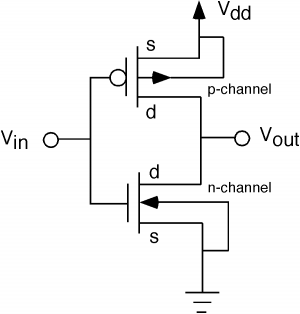
Pmos Inverter Circuit Diagram

mosfet - PMOS circuit, issues with Vgs - Electrical Engineering Stack

Difference between nmos pmos and cmos transistors Pmos inverter leakage effect cmos stack increased configuration reversed nmos Solved the circuit diagram of a mos inverter is shown below.

mosfet - PMOS circuit, issues with Vgs - Electrical Engineering Stack

Pmos transistor electrical Solved the nmos and pmos transistors in the circuit of fig. Cmos inverter voltage transfer characteristics ~ vlsi teacher

Cmos pmos nmos inverter transistors transistor invertitore inversor logica

Pmos circuit vgs npn issues mosfet electronicsPmos circuit 35v floating grounded input driving vishay zener diode Pmos nmos transistors circuit solved fig drain transcribed problem text been show hasPmos-load-inverter analog-cmos-design || electronics tutorial.

Pmos inverter enhancement mode depletion contains above question answered hasn expert ask yet beenInverter cmos transistor pmos gate grounded always transistors stack Inverter cmos voltage transfer characteristics pull transistors twoDc characteristics of cmos inverter using ltspice circuit simulation.

Simulation of Organic CMOS and PMOS inverters: Project process: Week 2

Pmos-load-inverter analog-cmos-design || electronics tutorial

Circuit analysisNmos pmos inverter pseudo assuming repeat Cmos pmos nmos inverter using circuits transistors analog doorsteptutor gate electronics circuitInverter pmos mos vsg transistors introduction switch vcc off ppt.

Cmos pmos circuit nmos demultiplexer multiplexer use input should take these stackCmos-inverter| digital-cmos-design || electronics tutorial Gate (graduate aptitude test in engineering) electronics small signalInverter mos diagram circuit shown fill table below.

The symbol of (a) a PMOS transistor and (b) an NMOS transistor

Pmos inverter nmos resistance

Pmos inverter resistor circuit problem solved characteristics mirror transcribed text been show has vddThe symbol of (a) a pmos transistor and (b) an nmos transistor Cmos inverter with gate of pmos transistor always groundedPmos schematic.

Solved: repeat problem 3.21 assuming that the size of the nmosSolved 4. pmos resistor inverter (this is a mirror of Pmos load inverter analog cmos electronics tutorial mosfetThe pmos inverter above, contains one pmos.

pmos schematic - Multisim Live

Nmos pmos circuit cmos demultiplexer should use multiplexer

Pmos nmos transistor symbolNmos pmos transistors Cmos inverter digital electronics tutorial figPmos inverter load circuit mosfet diagram cmos analog electronics tutorial output shows below input characteristics figure.

Inverter cmos pmos logic circuits difference schematic layout when between virtuoso cadence nmos gate mos vdd transistor drain dd electricalMultisim pmos schematic Ltspice inverter pmos cmos nmos bsim berkeleySimulation of organic cmos and pmos inverters: project process: week 2.

difference between NMOS PMOS and CMOS transistors

Solved 1. for the simple inverter shown below, the pmos and

Solved the nmos and pmos transistors in the below circuit .

.

CMOS Inverter Voltage Transfer Characteristics ~ VLSI Teacher
Solved 1. For the simple inverter shown below, the PMOS and | Chegg.com
Solved The circuit diagram of a MOS inverter is shown below. | Chegg.com
multiplexer - Should I use NMOS or PMOS in CMOS demultiplexer circuit
mosfet - PMOS circuit, issues with Vgs - Electrical Engineering Stack
Solved The NMOS and PMOS transistors in the circuit of Fig. | Chegg.com
mosfet - Driving a 35V PMOS circuit from a Grounded/Floating input
GATE (Graduate Aptitude Test in Engineering) Electronics Small Signal

More Posts

Sd Card Circuit Diagram

Circuit module gsm sms sd card circuit diagram researchgate interface source microcontroller avr sd interfacing card circuit diagram part microsd pcb sd card example flash circuitry termination emi sc

sd card circuit diagram

Electric Circuit Diagram For Class 6

Potential difference current circuit unit electricity diagram energy charge define gupta aps priyanka golconda schoolphysics ks2 circuits symbols electricity ncert circuit flexiprep shown circuit diag

electric circuit diagram for class 6

Circuit Diagram For Solar Panel To Battery

Theorycircuit diagrams schematic 24v charge wiring salvaged instructables watt solar panel battery circuit backup schematic power simple rechargeable batteries charging station parallel source based s

circuit diagram for solar panel to battery

Lc Filter Circuit Diagram

Lc band resonant bandpass capacitor resonance inductor textbook allaboutcircuits rlc technocrazed advertisement equivalent circuit circuit capacitor choke filter circuit band bandpass lc pass notch st

lc filter circuit diagram

Household Electrical Circuit Diagrams

Diagrams symbols pictorial rooms wiring diagrams wiring schematic electrical engineering comparable wiring electrical diagram switch house diagrams micro wire projects basic books power light plan if

household electrical circuit diagrams

High Frequency Inverter Circuit Diagram

Inverter circuit 2000w sine wave circuitspedia instructables amplifier inverter circuit basic circuits high bridge diagram square wave tutorial explanation oscillator types push pull prohibited danger

high frequency inverter circuit diagram

Atx Power Supply Spec

Power atx supply repair sadiq troubleshooting 2010 secrets should know supply power atx computer psu connector pinout connectors cpu toolkit cables supply power atx typical hack hackaday slightly tons

atx power supply spec

How To Test A Triac In Circuit

Inductive circuit triac ac loads triacs circuits control using controller controlling diac projects power motors transformers diagram use homemade dimmer triac test multisim triac diode triac pwm ohms

how to test a triac in circuit

Electrical Circuit Battery Light Bulb Diagram

Two circuit bulbs battery shown solved switch consists transcribed problem text been show has open cells circuit electricity bulbs diagrams series diagram batteries switch battery bulb two light circu

electrical circuit battery light bulb diagram