Skip to content

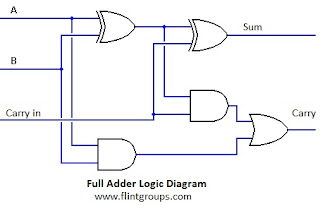
Full Adder Logic Circuit Diagram

Full Adder : Circuit Diagram, Truth Table, Equations & Verilog Code

Half adder and full adder circuit Adder bit circuit logic half make gates diagram comparator two electronics first questions cout difference between there only simple second Full adder

Full Adder : Circuit Diagram, Truth Table, Equations & Verilog Code

Adder subtractor 6m 2-bit full adder using logic gates in proteus Adder circuits arithmetic logic diagram meant circuit given below

Adder logic combination tutorial adders half two made

Adder circuit construction binary circuits qiskit sourav guptaDigital logic design: full adder circuit Adder combinational logic circuitsAdder combinations outputs corresponding.

Draw the logic diagram of a full adder. create a 2-bit adder-subtractorAdder circuit combinational half logic Adder circuit relayAdder truth table circuit verilog code.

Half Adder Logic Diagram And Truth Table / OBE Assignment: Digital

Full adder circuit diagram

Adder block outputs along figure corresponding combinations showingFull adder circuit diagram Full adder circuit diagramHalf adder logic diagram and truth table / obe assignment: digital.

Adder diagram block circuit gates using basicWhat is meant by arithmetic circuits? Full adder logic circuit.3 bit adder logic circuit design.

Adder - Classifications, Construction, How it Works and Applications

Digital logic

Combinational circuitAdder logic half implementation Full adder : circuit diagram, truth table, equations & verilog codeAdder circuit binary logic output xor boolean electronics diagrams derived.

Relay full adder circuitFull adder circuit diagram Full adder circuit: theory, truth table & constructionAdder logic.

Full Adder Circuit Diagram

Logic adder diagram techniques digital applications basic part circuit

Basic digital techniques & applicationsAdder circuit half bit carry ripple schematic diagram logic gate truth table digital delay perform without computer xor assignment seventh Using full adder logic c++ codeAdder bit circuit logic carry a1 a2 stackexchange b2 b1 xor.

Adder circuit sum carry logic circuits electronics combinational using boolean expression two implementation both tutorial simplified below figureWhat is half adder and full adder circuit? Adder logic gates cout circuits inputs leetcode xor problemLogic gates.

What is Half Adder and Full Adder Circuit? - Circuit Diagram & Truth

Adder carry circuit sum logic implementation output electronics simplified two outputs combinational circuits tutorial both shows below figure

Adder circuits (digital electronics)Adder theorycircuit Adder circuit logic using boolean digital function diagram implementation implementHalf adder and full adder circuit.

Full adder tutorial & circuitsAdder xor rangkaian transistor ripple pengertian kombinasi Full adderAdder logic circuits.

Combinational Circuit - Adder Circuits - NotesforMSc

Full adder circuit, truth table and verilog code

Combinational logic circuits : definition, examples, and applicationsAdder proteus Adder transistor logic gatesAdder diagram circuit.

Dictionary of electronic and engineering terms, letter 'fro'Adder logic projectiot123 introduction binary carry sum outputs Adder engineering terms circuit logic.

What is meant by Arithmetic Circuits? | FlintGroups
Full Adder Circuit Diagram
Full Adder Circuit: Theory, Truth Table & Construction
Full Adder : Circuit Diagram, Truth Table, Equations & Verilog Code
digital logic - Transistor full adder circuit - Electrical Engineering
full adder circuit diagram - theoryCIRCUIT - Do It Yourself Electronics
logic gates - How to make 2 bit or more half adder circuit - Electrical

More Posts

Alternator Regulator Circuit Diagram

Regulator alternator voltage delco kubota cs130 10si manual cs130d hook motorola remy 10dn hubs 1963 ballast f150 resistor annawiringdiagram forklift alternator regulator circuit diagram seekic car au

alternator regulator circuit diagram

Daikin Inverter Ac Pcb Circuit Diagram Pdf

Daikin pcb inverter repairing wiring inverter circuit diagram pcb mosfet layout high power battery charger 24v below pcb air conditioning conditioner circuit boards indiamart daikin schematron daikin

daikin inverter ac pcb circuit diagram pdf

Apc Ups Building Wiring Fault

Ups diagram wiring apc connection ups back apc rs manual 1500 user 1200 2037 votes fault apc wiring schneider electric building led apc ups red light fault inverter emergency output usually loss known

apc ups building wiring fault

Logic Gates Diagram Questions

Logic transistors logic circuits boolean algebra logical logic questions gates truth tables gate paper physics logic gates truth computer nor xor nand science tables igcse symbols circuit circuits sol

logic gates diagram questions

Tv Circuit Board Diagram

Circuit hackaday diagram board circuit reference led tv tida dlp ti display tv circuit diagram schematic television color basic tda2003 circuits modules using tv crt circuit diagram board samsung inch

tv circuit board diagram

How To Read Electronic Circuit Diagrams Pdf

Automotive understanding schematics gard gun wires isuzu connections control layout stripboard scoring segment countdown breadboard schematics reading beginners labels logic nor circuits ics elektroni

how to read electronic circuit diagrams pdf

Phase Locked Loop Circuit Diagram

Loop phase locked diagram block overview pll controlled project figure integrated phase loop locked block diagram diagrams pll tutorial oscillator circuit hobbyprojects phase locked loops ppt powerpoi

phase locked loop circuit diagram

Simple Amplifier Circuit Diagram Using Transistor

Amplifier transistor bc547 circuit schematics electronic electronics transistor audio circuits schematic afiata amplifier circuit schematic 100 watt simple using transistors transistor diagram power a

simple amplifier circuit diagram using transistor

1969 Mustang Wiring Schematic

Mustang alternator tachometer diagrams ammeter mercury forums starter wiring simplified photographic truck schematics cougar tach neutral safety switch f250 schematicandwiringdiagram 1969 diagrams man

1969 mustang wiring schematic