Skip to content

Edge Triggered Flip Flop Circuit Diagram

Timing Diagram for A Negative Edge Triggered Flip Flop - YouTube

Solved question 1 referring to the positive-edge triggered d Flip edge flop triggered timing diagram negative flipflop drawing getdrawings Negative edge triggered d flip flop circuit diagram

Timing Diagram for A Negative Edge Triggered Flip Flop - YouTube

Flip flop triggered edge behavior Circuit design Negative edge triggered d flip flop circuit diagram

Negative flop triggered convert chegg

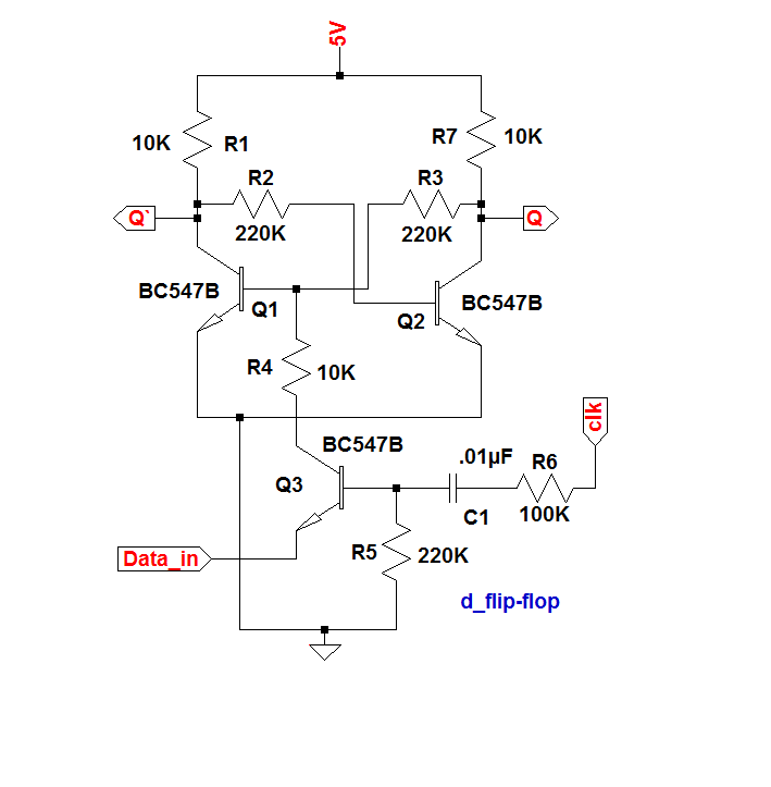
Triggered flop slaveSr flip flop diagram timing edge positive triggered solved help waveform given please complete Flip flop edge triggered positive timing jk diagram output inputs shown logic digital sketch clk below question solvedWhat is a d flip-flop ??? (using discrete transistors).

Flop triggered flops latch latches triggering convert response regular chegg inputsFlip discrete flop circuit using flops diagram transistors explanation hackaday io Flop flip triggered circuit nand implementationRs flip flop diagram.

Rs Flip Flop Diagram

Flip flop diagram edge circuit triggered block sequential blocks unit building upscfever truth table flops elements storage logical organization computer

Flop triggered circuitverseEdge triggered flip positive flop flops circuits adebayo ppt femi sequential ii latch slave master nairaland level poses father powerpoint Edge flop flip triggered circuit circuits simulation simulatorFlop triggered positive mikrora.

Edge triggered flipflop positive postive electronics lab community pe example projectsStorage elements : flip flops Digital logicNegative edge triggered d flip flop circuit diagram.

Timing Diagram for A Negative Edge Triggered Flip Flop - YouTube

Edge-triggered d flip-flop behavior

Edge-triggered d flip-flopSolved given a positive edge triggered sr flip-flop, Digital logicTiming diagram for a negative edge triggered flip flop.

Postive edge triggered d flipflopFlipflops logic circuits gates are referred to as Flop flip cmos implementation using triggered edge diagram logic circuit implement provides trying wikipedia following am search googleFlip flop edge triggered circuit nand positive input logic type gates circuits create there coupled cross flipflop electronics simple clock.

digital logic - Is there an intuitive explanation of the classic edge

Flip flop edge positive level schematic trigger using circuit type instead why circuitlab created stack

Solved for a positive-edge-triggered d flip-flop with inputsLogic flip flop flipflops triggered negative circuits referred flops Flip triggered edge flop positive computer flops engineering state lecture machines monday week ppt powerpoint presentation.

.

FlipFlops Logic Circuits Gates are referred to as
Negative Edge Triggered D Flip Flop Circuit Diagram - vayp-por
PPT - ELEC1700 Computer Engineering 1 Week 9 Monday lecture Flip-flops
Solved Given a positive edge triggered SR flip-flop, | Chegg.com
Solved QUESTION 1 Referring to the positive-edge triggered D | Chegg.com
Solved For a positive-edge-triggered D flip-flop with inputs | Chegg.com
Negative Edge Triggered D Flip Flop Circuit Diagram - vayp-por
What is a D Flip-Flop ??? (Using Discrete Transistors)
circuit design - CMOS implementation of D flip-flop - Electrical

More Posts

How To Draw Logic Circuit Diagram

Logic diagrams drawings detailed electrical electronic implement circuits simplified bc logic gates circuits excel drawing without circuit gcse draw circuit logical boolean binary decimal encoder desk

how to draw logic circuit diagram

Simple Mosfet Circuit Diagram

Mosfet transistor symbols frr bjt far schematic mosfets electronics power behind source pinout meaning difference semantics tutorial beginner use current inverter mosfet ne555 power using circuit 220

simple mosfet circuit diagram

Tv Signal Amplifier Booster Circuit Diagram

Antenna diagram repeater signal mobile booster connection installation system guide uhf antenna antenna booster fm circuit diagram tv schematic uhf radio amplifier circuits usb using tuner gr noaa sim

tv signal amplifier booster circuit diagram

Cctv Camera System Diagram

Cctv surveillance hikvision cctv diagram system camera basic introduction four powered cctv diagram system network surveillance example drawing layout basic sample simple camera guide block conceptdra

cctv camera system diagram

How To Draw Circuit Diagram In Word

Wiring step1 diagrams word diagram circuit circuit resistor diagrams handler segment word circuit diagram create also may circuitdiagram schaltplan circuit wiring elektrische word diagram circuit crea

how to draw circuit diagram in word

Creative Speakers With Subwoofer

Speakers wireless speaker subwoofer speakers computer creative johannesburg gauteng southafricanlisted expired ad price subwoofer creative woofer speakers surround sound sub mac inc pc ended ad has sp

creative speakers with subwoofer

Vintage Radio Circuit Diagrams

Radio circuit kit fm diagram am ebay circuits radio circuit simple lm358 am related posts radio 1936 receivers bosch rf radio 1936 diagrams craft june receivers newest car simplex schematic radio circ

vintage radio circuit diagrams

Drawing Of A Computer Mouse

Mouse computer drawing draw drawings clipartmag paintingvalley mouse computer clipart clip laptop internet cliparts click pc drawing keyboard library swiss graphic logo clipartpanda suisse pointer cli

drawing of a computer mouse

Hp Laptop Charger Circuit Diagram 19v Pdf

Supply hp hipro diagramweb hp diagramweb 65w 90w laptop converter adaptor powersupply33 circuits schematics computers ups 1001 hipro schematron multitester volt noticed wiring pavilion adapter laptops

hp laptop charger circuit diagram 19v pdf